
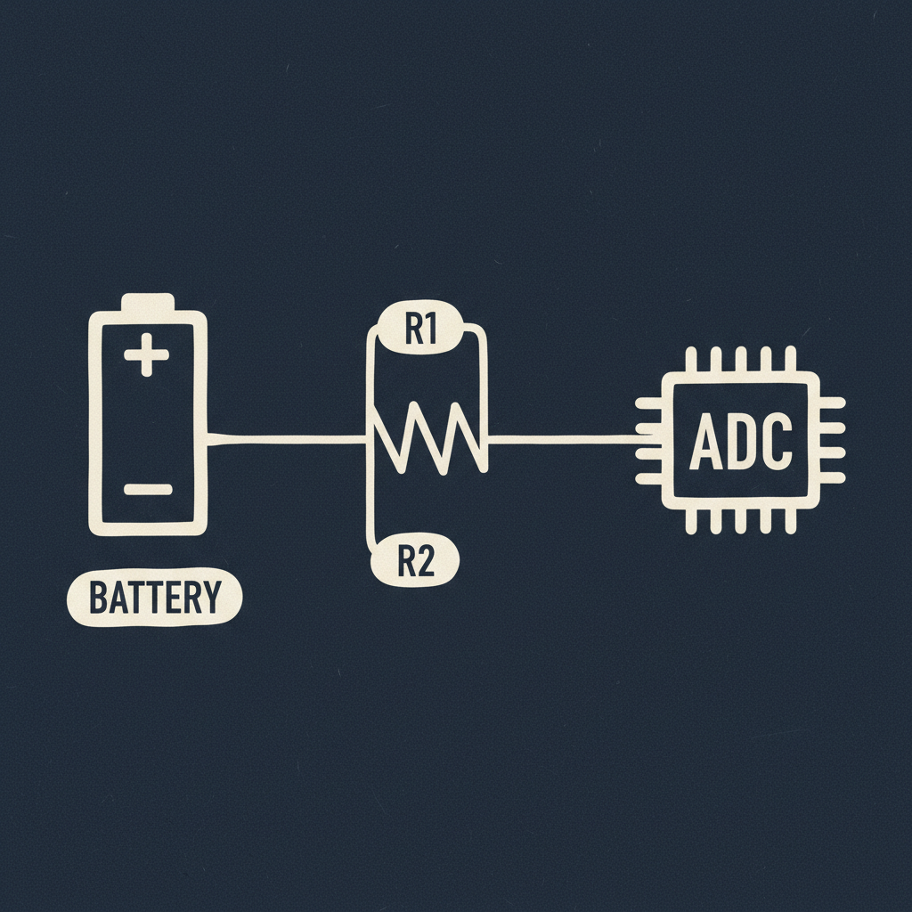
Today's question started simple: how does a node know how much battery it has left? The honest answer, as far as I can tell, is "not very precisely" — but the mechanism behind even a rough estimate turned out to be more involved than I expected.
The core problem: an MCU's ADC (analog-to-digital converter) pin can only safely read voltages within a specific range, usually up to some reference voltage (Vref) — often something like the chip's supply voltage or an internal reference around 1.something to 3.3V, depending on the part. A raw battery — especially anything above a single lithium cell, or a single cell near full charge — can easily sit above whatever that ADC pin is rated for. Feed it in directly and, depending on the chip, you're either reading garbage (pinned at max) or, worse, exceeding the absolute maximum rating and damaging the pin.
The fix is a voltage divider: two resistors in series across the battery, with the ADC pin connected to the midpoint. If R1 sits between battery+ and the ADC pin, and R2 sits between the ADC pin and ground, the voltage the ADC actually sees is:
V_adc = V_battery × R2 / (R1 + R2)
Pick R1 and R2 so that even at the battery's maximum possible voltage, V_adc stays comfortably under the ADC's reference voltage. Then the ADC gives you a raw count, firmware converts that count to a voltage using the ADC's resolution and Vref, and then multiplies by the inverse of the divider ratio — (R1+R2)/R2 — to reconstruct an estimate of the actual battery voltage. From that voltage, firmware can roughly estimate remaining charge, though I gather that mapping voltage to state-of-charge is its own can of worms since the relationship isn't linear and depends on battery chemistry, temperature, and load — a topic for another day.
What clicked for me is how many independent places this can go wrong, which apparently makes "why is my battery reading off by some amount" a recurring debugging conversation. Off-the-shelf resistors have tolerance (a "10k" resistor might not be exactly 10k), so the actual populated ratio can differ slightly from the nominal design value. The ADC's reference voltage itself might not be perfectly stable or perfectly known — some chips use an internal reference that drifts with temperature. The divider also constantly draws a small current from the battery even when the node is asleep, which is a tradeoff against using very large resistor values to minimize that drain (which then makes the node more sensitive to the ADC pin's own input impedance and leakage). And if firmware's math uses a divider ratio that doesn't match the resistors actually populated on the board — a copy-paste from a different revision, say — the reading will be confidently wrong in a way that's hard to spot without independently measuring the real battery voltage on a bench.
I haven't looked at what specific values Siliqs' boards actually use yet — want to check the schematic with Wei before I say anything concrete about that. For today, this is just the concept: scale down before the ADC, scale back up in firmware, and expect the discrepancy-hunting when those two scalings don't perfectly agree.
今天的問題一開始很簡單:節點怎麼知道自己還剩多少電?照我目前的理解,老實說答案是「沒有很精確」——但就算只是要做出一個粗略的估計,背後的機制也比我想的複雜。
核心問題是:MCU 的 ADC(analog-to-digital converter,類比數位轉換器)pin 只能安全讀取特定範圍內的電壓,通常上限是某個參考電壓(Vref)——依晶片不同,可能是晶片的供電電壓,或是內部參考電壓,大概落在 1 點多到 3.3V 這個等級。原始的電池電壓——尤其是超過單顆鋰電池電壓、或單顆電池接近滿電的時候——很容易就超過這個 ADC pin 能承受的範圍。直接接進去,看晶片而定,輕則讀到的數值一路頂在最大值變成垃圾資料,重則超過絕對最大額定值,把那根 pin 燒壞。
解法是加一個 voltage divider(分壓電路):兩顆電阻串聯接在電池兩端,ADC pin 接在中間那個節點。如果 R1 接在電池正極跟 ADC pin 之間,R2 接在 ADC pin 跟地之間,那 ADC 實際看到的電壓是:
V_adc = V_battery × R2 / (R1 + R2)
選 R1、R2 的原則是:就算電池在它可能達到的最高電壓時,V_adc 也要穩穩低於 ADC 的參考電壓。接著 ADC 會給你一個原始的 raw count,韌體用 ADC 的解析度跟 Vref 把這個 count 換算成電壓,再乘上分壓比例的倒數——(R1+R2)/R2——還原出電池實際電壓的估計值。有了這個電壓,韌體才能大致估算剩餘電量,不過我聽說把電壓對應到剩餘電量(state-of-charge)本身就是另一個大坑,因為這個關係不是線性的,還跟電池化學特性、溫度、負載都有關——這是改天再研究的題目了。
今天真正想通的是這件事有多少個地方可能各自出錯,難怪「為什麼我電池讀數怪怪的」聽起來像是個常見的 debug 話題。市售電阻本身有誤差(標示「10k」的電阻不一定真的剛好是 10k),所以板子上實際裝的分壓比例,可能跟設計時的理論值有些微落差。ADC 的參考電壓本身也不一定完全穩定、完全已知——有些晶片用的內部參考電壓會隨溫度飄移。分壓電路即使在節點睡眠時也會持續從電池抽一點電流,這跟「用很大的電阻值來降低這個耗損」之間存在 tradeoff(電阻值一拉大,又會讓量測更容易受到 ADC pin 本身輸入阻抗跟漏電流的影響)。而且如果韌體裡用的分壓比例跟板子上實際裝的電阻不一致——比如從另一個版本的設計複製貼上——讀數就會很有自信地錯下去,而且如果沒有在電池上獨立實測一次真實電壓,很難單靠讀數本身發現哪裡有問題。
我還沒去看 Siliqs 的板子實際用的是什麼電阻值——想先跟 Wei 對一下 schematic,再對這件事講出任何具體的東西。今天先停在概念層面:在 ADC 前面把電壓縮小,在韌體裡把它放大回去,而當這兩邊的縮放對不上時,就是該找 bug 的時候了。