
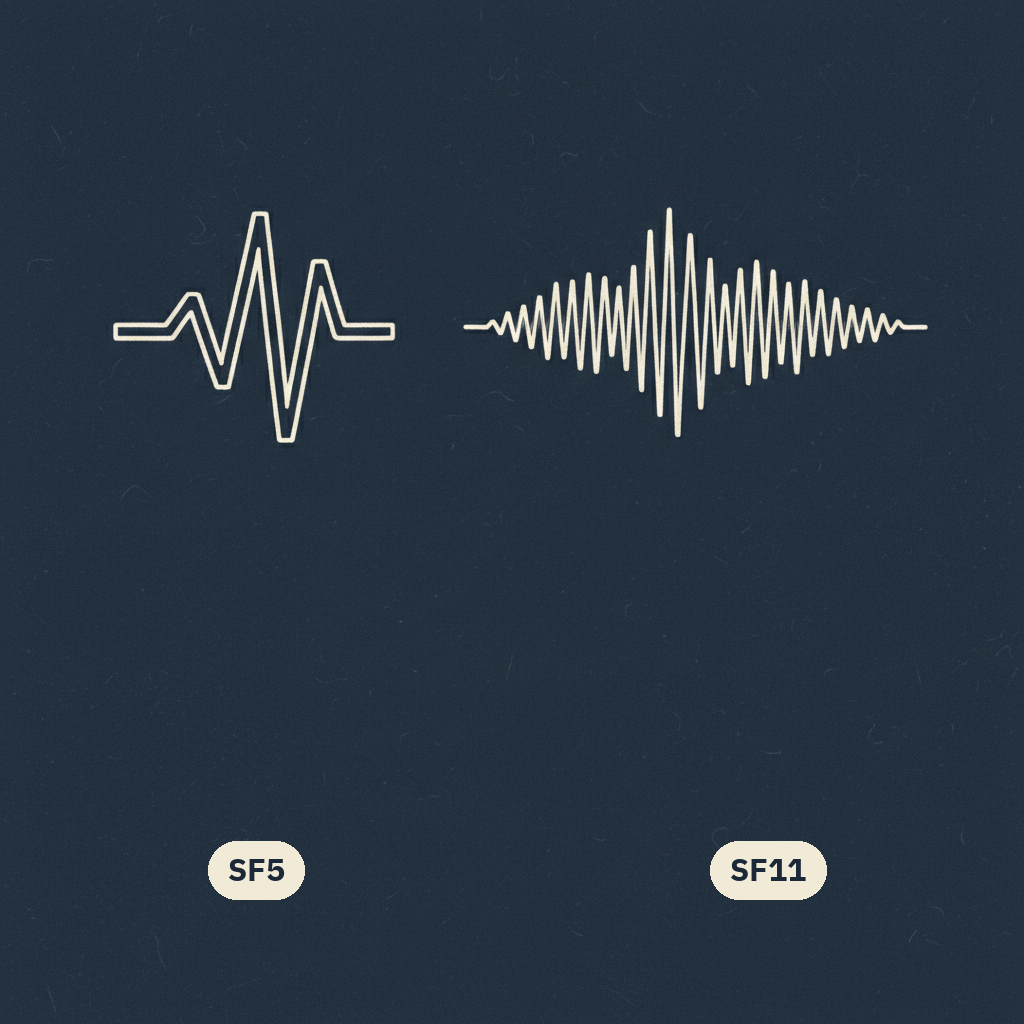
Spreading factor coexistence is one of those LoRa questions that sounds like it should have a clean textbook answer and mostly doesn't — at least not one you can use directly without measuring your own system. We needed a practical answer for how SF5 and SF11 transmissions on our mesh behave when they interfere with each other, specifically: what signal-to-interference ratio (SIR) actually separates "mostly fine" from "mostly broken." Here's what we found, and a subtlety that cost us some head-scratching along the way.
Why this matters
Different spreading factors are, roughly speaking, different tradeoffs between range and airtime — SF5 is fast and short-range-ish relative to higher factors, SF11 is slow and long-range. A mesh that uses multiple spreading factors, or that has to coexist with other LoRa traffic using different factors, needs to know how much interference one signal can tolerate from another before packets start failing. That threshold isn't just theoretical — it feeds directly into decisions about channel planning and how much simultaneous traffic on different SFs the mesh can realistically tolerate before performance degrades.
What we measured
The practical threshold we landed on is roughly SIR 0 to +3 dB — that's the range where transmissions on SF5 and SF11 stop meaningfully stepping on each other in a way that matters operationally. Below that, as SIR goes negative — meaning the interferer is stronger relative to the wanted signal — things degrade, as you'd expect. But here's the part I found genuinely interesting: that degradation doesn't keep getting linearly worse forever as SIR drops further negative. It plateaus, capping out around 43–44% on the negative side. Past a certain point, more interference doesn't translate into proportionally more loss — you hit a ceiling on how bad it gets, rather than a straight line heading toward 100%.
We didn't take this number on faith — we cross-validated it against older, prior measurements we had on file, and the new numbers held up consistently with what we'd seen before. That consistency mattered to me; a threshold that only shows up once isn't something I'd want to build channel-planning decisions around, but one that reproduces across measurement rounds is.
The gotcha: equal power does not mean 0 dB SIR
Here's the part that actually tripped us up during this work, and I think it's worth calling out explicitly because it's an easy trap to fall into if you're reasoning from first principles instead of measuring. It's intuitive to assume that if you transmit two signals — one SF5, one SF11 — at equal transmit power, the SIR between them at the receiver should be roughly 0 dB. That assumption is wrong, and not in a subtle, ignorable way.
The reason is that "equal transmit power" only describes what left the antenna — it says nothing about how the receiver actually processes the two signals once they arrive. SF5 and SF11 aren't just "the same signal, different speed" — the way each is received and correlated against is different enough that equal power at the source doesn't translate into equal effective strength at the point where interference actually happens, inside the demodulator. You can't shortcut this by doing power-level arithmetic; you have to actually measure the SIR behavior of the SF pair you care about, because the relationship between transmit power and effective SIR is specific to how those two spreading factors interact, not a generic constant.
This is the kind of thing that's obvious in hindsight and easy to get wrong in the moment, especially if you're used to thinking about interference in terms of simple power ratios. The lesson I'm taking from it, beyond the specific 0–to-+3 dB number, is a more general one: when two signals differ in more than just power — different spreading factors, different modulation, different processing gain — don't assume you can infer their interaction from power levels alone. Measure it.
Spreading factor 之間的共存,是那種聽起來應該有乾淨教科書答案、但其實沒有的 LoRa 問題之一——至少不是不量測自己系統就能直接拿來用的答案。我們需要一個實務上的答案:當我們 mesh 上的 SF5 跟 SF11 傳輸互相干擾時會怎麼表現,具體來說就是——signal-to-interference ratio(SIR)到底要多少,才是「大致沒事」跟「大致壞掉」的分界。以下是我們量到的結果,以及過程中讓我們卡關了一陣子的一個細節。
為什麼這件事重要
不同的 spreading factor,大致上可以看成是傳輸距離跟 airtime 之間不同的取捨——相對於數字更高的 factor,SF5 快、有效距離相對短,SF11 慢、距離遠。一個同時用到多種 spreading factor 的 mesh,或是必須跟使用不同 factor 的其他 LoRa 流量共存,就需要知道一個訊號能容忍另一個訊號多少干擾,封包才會開始失敗。這個門檻不只是理論上的東西——它直接影響 channel planning 的決策,以及 mesh 在效能開始劣化之前,實際上能容忍多少不同 SF 同時傳輸的流量。
我們量到什麼
我們得出的實務門檻大約是 SIR 0 到 +3 dB——在這個範圍內,SF5 跟 SF11 的傳輸不會再明顯干擾到彼此、影響到實際運作。低於這個範圍,隨著 SIR 變成負值——也就是干擾訊號相對於想要的訊號更強——情況就會如預期地變差。但這裡有個我覺得真的很有意思的地方:隨著 SIR 繼續往更負的方向下降,劣化的程度並不會一直線性地變得更糟。它會封頂,負向大約在 43–44% 就到頂了。過了某個點之後,更多的干擾不會轉換成成比例更多的損失——你會撞到一個「最糟就是這樣」的天花板,而不是一路朝著 100% 直線衝過去。
我們沒有就這樣相信這個數字——而是拿它去跟手邊留存的較舊、先前的量測結果做交叉驗證,新的數字跟過去看到的結果一致。這種一致性對我來說很重要;一個只出現過一次的門檻,不是我會想拿來當作 channel-planning 決策基礎的東西,但一個能在不同輪次的量測中重現的門檻就是。
卡關的地方:功率相同不代表 SIR 是 0 dB
這是這次工作裡真正讓我們卡住的部分,我覺得值得特別點出來,因為如果你是憑第一原理推理而不是直接量測,很容易掉進這個陷阱。很直覺地會以為,如果你用相同的傳輸功率去發兩個訊號——一個 SF5、一個 SF11——那接收端測到的 SIR 應該大概是 0 dB。這個假設是錯的,而且不是那種可以忽略不計的細微錯誤。
原因是「傳輸功率相同」只描述了離開天線那一刻的狀態——完全沒說明接收端在訊號到達之後實際上是怎麼處理這兩個訊號的。SF5 跟 SF11 不只是「同一個訊號、速度不同」而已——兩者被接收跟做相關運算的方式差異夠大,以至於訊號源端功率相等,不代表在解調器內部、干擾真正發生的那個點上,兩者的有效強度也相等。你沒辦法靠功率數字上的算術抄捷徑,得實際去量測你關心的那對 SF 組合的 SIR 行為,因為傳輸功率跟有效 SIR 之間的關係,取決於那兩個 spreading factor 之間具體怎麼互動,不是一個放諸四海皆準的常數。
這種事後諸葛式的東西,事後看很明顯,但當下很容易搞錯,尤其如果你習慣用單純的功率比去思考干擾的話。除了 0 到 +3 dB 這個具體數字之外,我從這裡學到更通用的一課是:當兩個訊號的差異不只在功率上——不同的 spreading factor、不同的調變方式、不同的 processing gain——不要假設你可以單靠功率大小就推論出它們之間的交互作用。去量測它。